Nerf Stampede external power and auto-fire
Published: April 18, 2011 00:46
Time Estimates
Novice: a day
Advanced: 3-4
hours
Expert: 2 hours
Intro
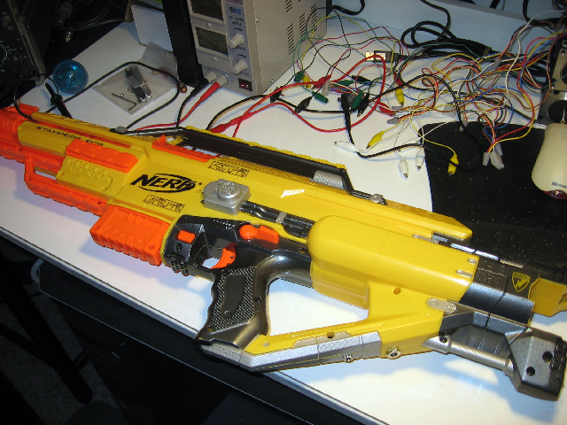
Nerf's new Stampede is a pretty cool toy. It fixes
several of the flaws from the Vulcan
(most notably the easily-jammed belt
feed mechanism), and it comes with a faceplate which is great if you ever
need to build a last-minute Aztec sun god costume for Halloween.
However, it's still missing two very important
components for a hobbyist engineer: first, it has no way to draw external
power. The gun is a complete beast with six D cell batteries weighing the gun
down like it was made of all your crushed hopes and dreams, and it
would be nice to shift some of that weight out of the case. Second, it
has no way to initiate firing automatically from a source other than the
trigger--like a turret, a drone, or some crazy sci-fi
brain-interface device.
Well, it's time to fix that.
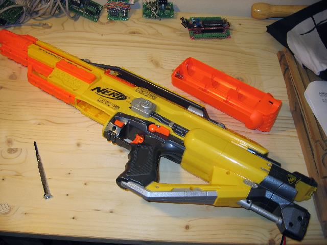
To start with, you'll need to remove the ammo clip,
battery sled, and any ridiculous accessories you may have attached to the gun,
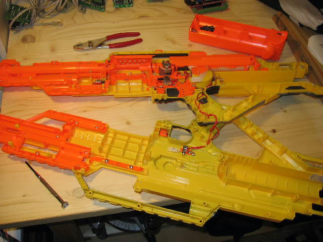
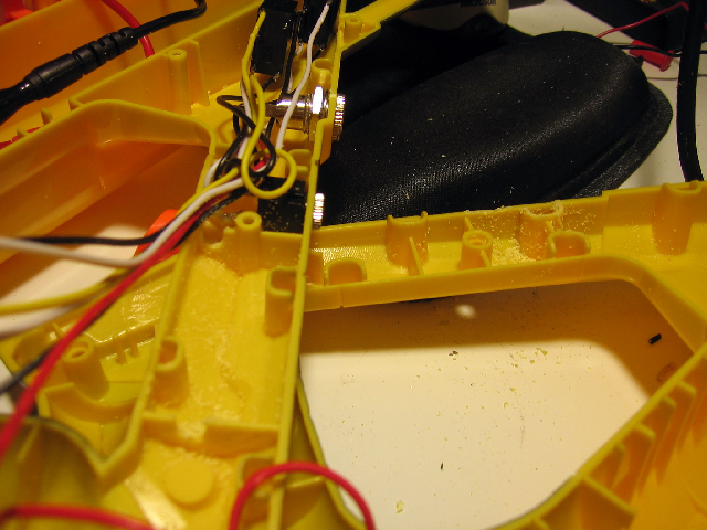
then take out all 34(!) screws. Crack the case open and look inside to see
what you'll be dealing with for the next few hours.
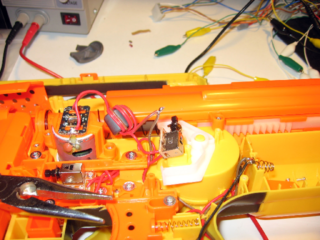
The wiring makes a pretty simple circuit: in brief,
there's a long series of switches which all have to be closed before the motor
will move the plunger back and fire. The last of these switches is the
trigger, which is a DPDT
switch whose default state shorts the two wires leading to the motor.
Power
First things first: external power. This is a pretty
simple one. I wanted to make sure that the gun would still only be on if the
power switch was flipped, so it's simply a matter of soldering two more wires
into the gun.
First find the battery terminal that leads to ground; it
should be the one that's more easily accessible and has a brownish-gray wire
running from it. Take a length of wire and solder it to that terminal
(make sure it's long enough to reach to
the rear of the gun after looping around through the handle).
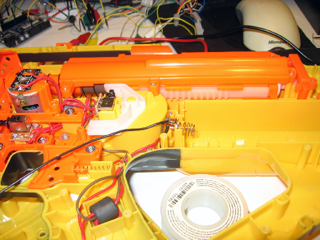
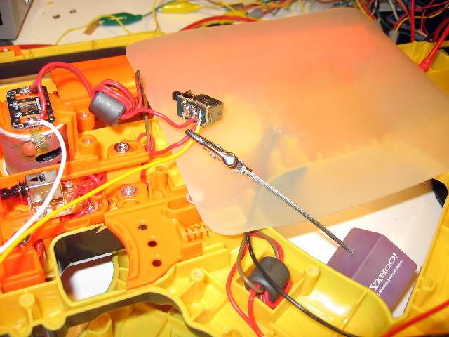
Second, find the power switch. This is the only piece
attached to the part of the gun that you lifted off. It should have three
terminals, two of which have wires. Take another length of wire (again,
long enough to reach to the rear of the gun), pick the terminal wth the wire
attached to the other battery terminal, and solder your new wire onto
that.
(Extra credit: If you want to have the gun fire anytime
regardless of the position of the power switch, solder the wire to the
middle terminal of the switch. If you want to have it fire only when the switch is
set to off (so you can choose battery or external power), solder it to the
third terminal with nothing attached to it.)
(Super-extra credit: Your life will probably be easier if
you just cut the wires to the switch and attach a header and socket that you
can easily detach. Then you can set the other half of the Stampede aside and
just work with the interesting half. In this case, you would obviously solder
the two power wires to the same header pin, rather than to the switch.)
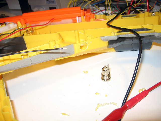
Now comes the time to be destructive to our Nerf guns.
We're going to drill a hole so we can attach the power jack to the gun. If
you use the same part I used, it may require up to a 29/64 drill bit. I
recommend drilling through the bottom of the gun toward the rear, just
after the silver turns to yellow. Start with a small bit to drill a
starter hole and work your way up.
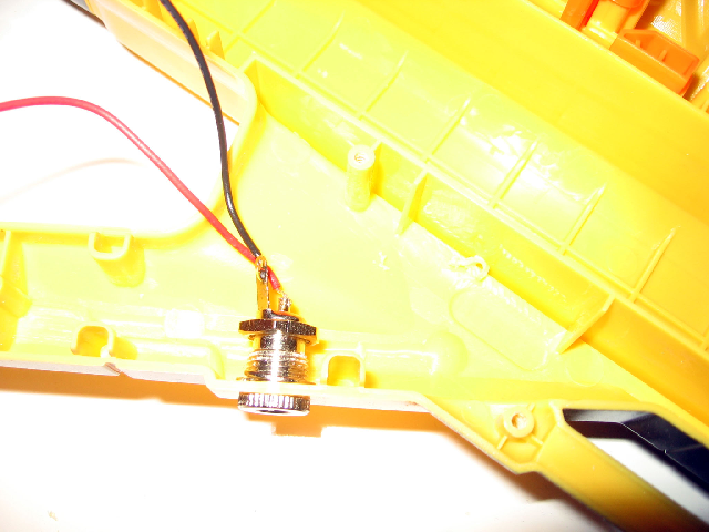
Solder your two wires to the jack (ground is on the
outside), twist the nut onto the end, and you're done!
Firing Control
When I first saw how the trigger switch
was wired to the motor, I wondered why the two
motor wires were shorted out by default in the first place. Theoretically, if
the switch was slid to its natural position and the current from
power to the motor was cut, the motor should stop spinning;
attaching the ground to the switch made no sense to me. So I fixed
it.
Cut the ground wires off of the switch and give them
a twist together so they're attached--don't solder them just yet (we'll
get to that later).
Now if you pull the trigger you'll notice a curious
thing which I'm still at
a loss to explain. With the ground wires detached from the switch, you
can pull the trigger and the gun will fire... but it won't stop. The
plunger will keep going until the power runs out, and if you've already
completed the external power hack and have this hooked up to a bench
supply, that could be a while.
So here's the ideal situation: this could
be solved with a couple of transistors--one JFET that would pass
current by default except when a voltage is applied to its gate, and one
N-channel MOSFET that
doesn't pass current except when voltage is
applied to its gate. However, transistors are still a little bit
like mystic incantations to me, so we'll go with the kludgier route:
relays.
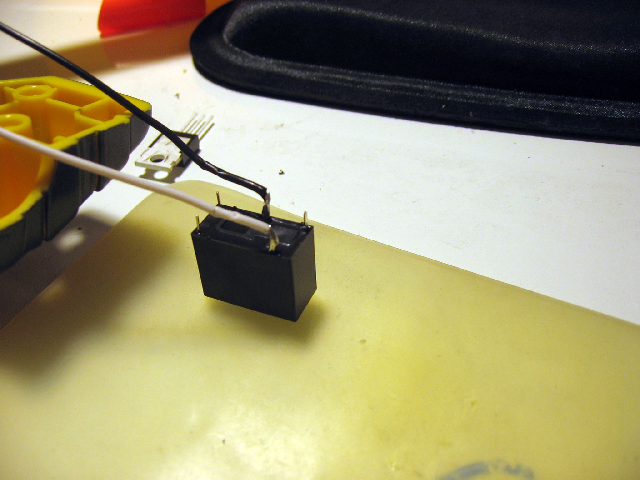
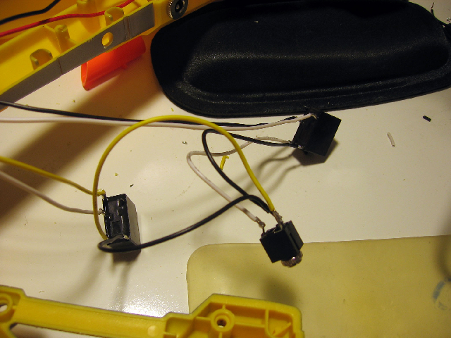
The good news is that we can use the same relay for
each of these situations. Mouser sells
some perfectly serviceable SPDT
relays for cheap which--while admittedly bulky--get the job done just
fine.
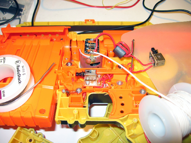
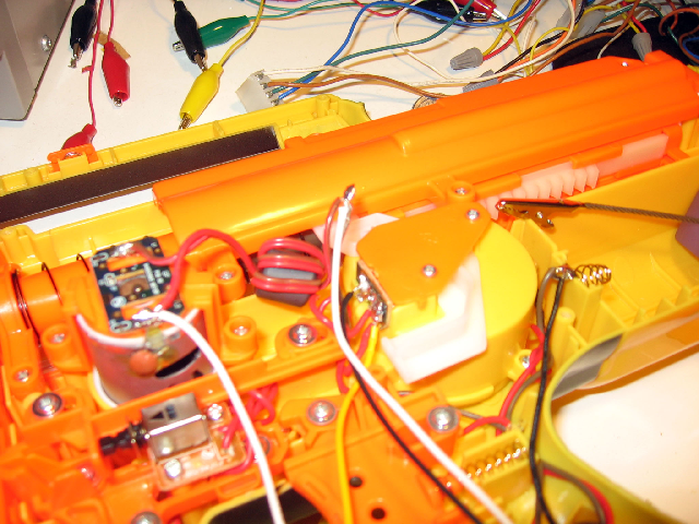
We'll need four wires attached to various places
around the trigger/motor assembly. The first should go to the positive
terminal of the motor. Make sure this is long enough to snake under the
trigger assembly, down the handle, and to the back of the gun. When in
doubt, make the wire longer than you need; you can trim it later.
Next solder another wire to the bottom terminal of
the trigger switch.
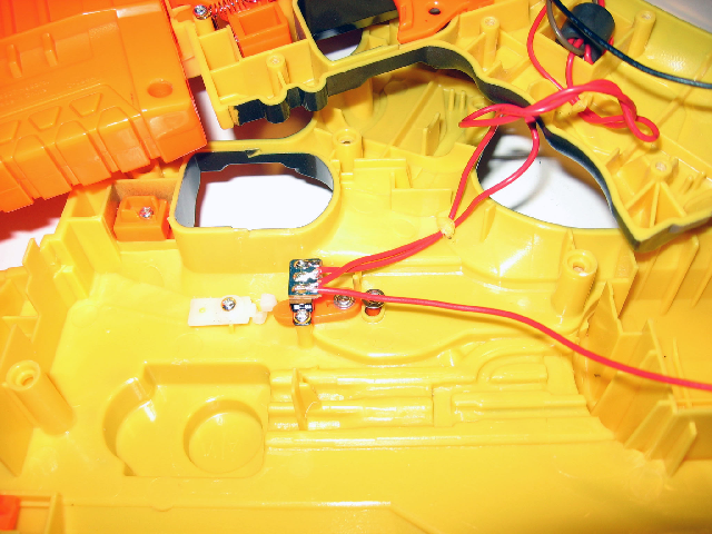
Now solder two more wires to close the ground-switch
connection. One will be attached to the two ground wires you cut and
twisted together earlier (you can solder them all together now), and the
other will be attached to the switch terminal that you cut them off
of.
Attach the power leads to the common and N.O.
terminals of one of the relays; it doesn't really matter which order
they're in.
Do the same for the ground wires you soldered, except
these instead go to common and N.C.
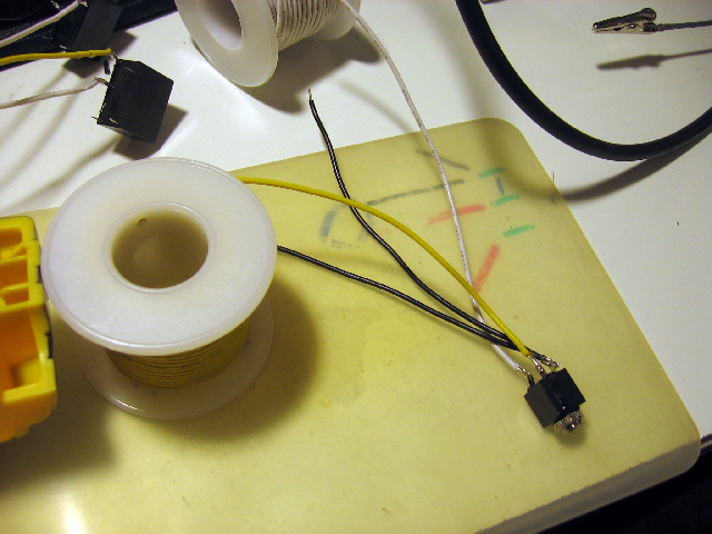
Now things start getting squiggly. Take the headphone
jack (you did get a TRS
connector, right? Good). Solder two ground
wires to the outermost terminal (on mine, this was the middle one), and solder
one more wire to each of the other terminals. You should have four wires
in total, two attached to ground.
Take one of the non-ground wires and solder it to a
switch terminal on one of the relays--take a ground wire and solder it
to the other switch terminal. As far as I know, these switches don't
care about polarity, so they should work equally well regardless of the
orientation of the wires.
Take the remaining non-ground and ground wires and do
the same on the other relay. You should now have two fully functioning
relays ready to be switched by a microcontroller.
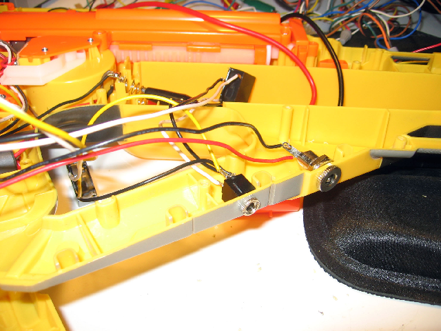
Drill another hole slightly down the handle flyaway
from the power jack. For the headphone jack, I used a 1/4 bit. Stick the
headphone jack in the hole (which may take some creative use of
needlenose pliers and abusing the newly-soldered wires as handles), and
spin the locking nut on. Be warned when drilling the hole, however:
if you drill the hole too close to the support post (like I did
here) then you'll have to file down the interlocking support post on the
other half of the gun.
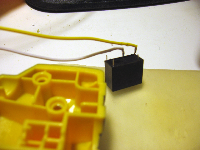
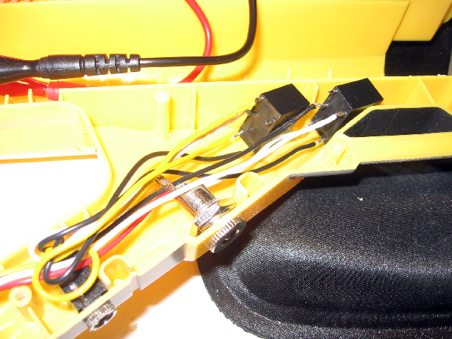
Shove the two relays up into the
rear handle cavity. Tack them down with a bit of glue if you wish, but I
find that the wires keep them in place pretty well.
You would be done except for one lingering issue.
The structure of the Nerf gun is such that when it's sealed up,
several of the reinforcing shims will cut the wires. We'll have to file
grooves in them for the wires to fit into when the gun casing is closed
up. I recommend a rounded file if you have one, but any small file will
probably do.
Congrats! Test the final weapon before starting to
seal it up. Put the case on and test it again. Put in a few screws
around the handle and trigger area and test it again. Put a few more
screws and test, test, test. You really don't want to put in all 34
screws and then test the weapon only to find that something broke in the
reassembly and you have to take out all those screws again. Believe
me--I did it.
Now you can solder some leads onto the headphone and
power connectors and wreak havoc!